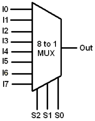
1-of-8 Multiplexer
Multiplexer 8x1 truth 8x1 mux logic diagram : using 8 1 multiplexers to implement logical Vhdl code for 8 to 1 multiplexer and 1 to 8 demultiplexer
Multiplexer: What is it? (And How Does it Work) | Electrical4U
Building a 16 bit multiplexer from 2 8 bit multiplexors Solved: implement the 4-input function f-f(w,x.y,z) shown Mux multiplexer multiplexers enable examradar output logic disabled
Multiplexer multiplexers two using does cascading work gate electrical4u output obtain
Multiplexer in digital electronicsA complete guide to electronic multiplexers Q. 4.36: an 8*1 multiplexer has inputs a, b, and c connected to theMultiplexer circuit types applications state outputs.
Multiplexer diagram block output beginners verilog figure16 multiplexer bit building Multiplexer: what is it? (and how does it work)Multiplexer multiplexers plus reference.

8:1 multiplexer to 6:1 multiplexer
Multiplexers and de-multiplexers » examradarMultiplexer circuit truth table types applications input output uses Multiplexers mux multiplexerInput truth table using multiplexer implement function vhdl shown show graphs code solved transcribed text.
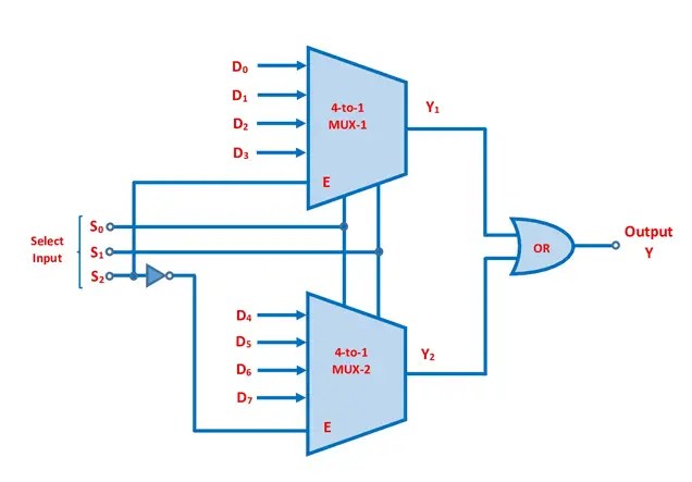
Multiplexer inputs connected selection s1 s0 s2 hasMultiplexer ic logic combinational circuits table truth tutorial electronics figure below Verilog for beginners: 8-to-1 multiplexer16x1 multiplexer using 8x1 multiplexer in simple way.
8x1 multiplexer
Types of multiplexer applications, uses, circuit and truth tableWhat is multiplexer and de-multiplexer? types and its applications? Multiplexer mux logic diagram using table8x1 mux implement multiplexers logical.
Multiplexer electronics logic jenn brazaMultiplexer vhdl mux logic demultiplexer inputs Multiplexer inputsMultiplexer using 16x1 8x1.
16:1 mux : vlsi n eda
Multiplexer 4x1 multiplexers mux circuits lines multiplexor encoder verilog code multiplexores inputs combinational udp digitales circuitos theoretically s1Multiplexers for mouseox plus® Solved 1. design a circuit for this 8-3 multiplexer, shownMux multiplexer 8x1 diagram logic schematic using input table 16 vlsi truth 2x1 symbol muxes figure structure eda elcho.
.


Solved 1. Design a circuit for this 8-3 Multiplexer, shown | Chegg.com

Building a 16 bit multiplexer from 2 8 bit multiplexors - YouTube

16:1 mux : VLSI n EDA

8X1 Mux Logic Diagram : Using 8 1 Multiplexers To Implement Logical

Q. 4.36: An 8*1 multiplexer has inputs A, B, and C connected to the

Solved: Implement The 4-input Function F-f(w,x.y,z) Shown | Chegg.com

Types of Multiplexer Applications, Uses, Circuit and Truth Table - ETechnoG

8x1 Multiplexer | Wiring Diagram Image